Vitron SM26 Smart TV - HDMI Port Repair with Trace Reconstruction
Vitron SM26 with damaged HDMI port from botched previous repair attempt. Advanced trace repair using magnet wire jumpers and precision micro-soldering.

Symptoms
- HDMI port physically broken/loose
- Multiple lifted pads from previous repair attempt
- No signal on HDMI input
- Port was previously 'repaired' by another technician
Diagnosis
Customer brought in the TV after another repair shop attempted to replace the HDMI port and made it worse. Visual inspection under microscope revealed a disaster: 6 out of 19 pads were completely lifted (torn off the PCB), the old HDMI port was still partially attached with cold solder joints, and there was flux residue everywhere. The lifted pads meant the copper traces were exposed but the solder pads themselves were gone. This is a challenging repair because you can't just solder a new port - you need to rebuild the electrical connections using jumper wires. Traced each lifted pad to find where the PCB trace goes (usually to a nearby component or via). This repair requires advanced micro-soldering skills and 38AWG magnet wire.
- Stereo Microscope (essential - 10x-40x magnification)
- Hot Air Rework Station
- Fine-tip Soldering Iron (Hakko FX-888D or similar)
- 38AWG Magnet Wire (ultra-thin enameled copper wire)
- Flux Gel (high quality)
- Solder Wick
- Tweezers (ESD-safe)
- Multimeter with continuity beeper
- Isopropyl Alcohol 99%
- HDMI Port Connector19-pin Type A SMDMust match original footprint exactly
- 38AWG Magnet WireEnameled copperFor jumper wire repairs
- UV Solder MaskGreen or clearOptional - to protect jumper wires
Repair Process
Remove the Damaged Port and Clean the Mess
Use hot air (380°C) to remove the partially attached HDMI port. Clean all the old solder and flux with solder wick and isopropyl alcohol. Under the microscope, identify which pads are lifted and which are intact. In this case, pads for pins 1, 4, 7, 10, 15, and 19 were completely gone. Document everything with photos.
Trace the Lifted Pads
This is detective work. For each lifted pad, follow the PCB trace to find where it goes. Use a multimeter in continuity mode to trace from the HDMI pin location to nearby components. For example, pin 19 (Hot Plug Detect) usually goes to a pull-up resistor. Pin 1 (TMDS Data2+) goes to an ESD protection diode. Mark each destination point.

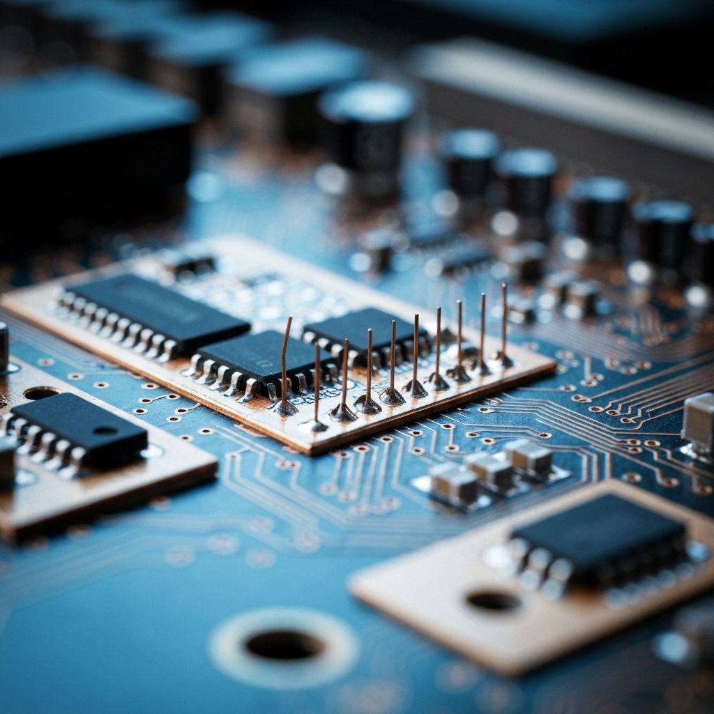
Run Magnet Wire Jumpers
This is the most delicate step. Cut 38AWG magnet wire to length (keep it as short as possible). Burn off the enamel coating on the ends with your soldering iron. Solder one end to the HDMI port pin and the other end to the destination point you traced. Use LOTS of flux. Work under the microscope. Each wire must be individually soldered and tested for continuity. In this repair, we ran 6 jumper wires.
Install the New HDMI Port
Once all jumper wires are in place, position the new HDMI port. Solder the intact pads first to mechanically secure it. Then carefully solder the pins that have jumper wires - don't disturb the jumpers. Solder the shield tabs for mechanical strength. This step requires a very steady hand.
Test Every Connection
Use a multimeter to test continuity from each HDMI pin to its destination. All 19 pins must have good continuity. Check for shorts between adjacent pins (should be infinite resistance). Plug in an HDMI cable and test with a device. The TV should detect the signal immediately. Test all HDMI functions: video, audio, CEC, ARC.

Conclusion
This repair saved a TV that most technicians would have declared unrepairable. The key to success was patience, proper tools (especially the microscope), and systematic tracing of each connection. The jumper wires are actually more reliable than the original PCB traces because they're point-to-point connections with no vias or weak solder joints. Total repair time: 3 hours. This is an advanced repair that requires micro-soldering experience, but it's absolutely possible with the right approach.