Smart 82" Royal TV - Dead Power Supply Resurrection
Massive 82-inch HDTV completely dead with no standby light. Traced power supply failure through optocoupler feedback loop to restore functionality.

Symptoms
- Completely dead - no standby light
- No response to power button
- No clicking or sounds from power supply
- Fuse is intact
Diagnosis
This is a tricky one because there were no obvious visual clues. Fuse was good, no burnt components, no bulging capacitors. Measured the primary side - AC voltage was present at the bridge rectifier and the main filter capacitor showed 320V DC. This meant the primary side was working. Checked the secondary side - all voltage rails read 0V. This pointed to a regulation/feedback problem. In switching power supplies, the feedback loop tells the controller IC how much power to deliver. Tested the optocoupler (PC817) which isolates the secondary side feedback from the primary controller. The LED side (pins 1-2) showed correct forward voltage drop of 1.2V, but the transistor side (pins 3-4) showed infinite resistance in both directions - it was open circuit. A failed optocoupler means the controller gets no feedback and shuts down for safety.
- Multimeter (essential)
- Soldering Iron
- Desoldering Pump
- Component Tester (optional but helpful)
- Oscilloscope (for advanced diagnosis)
- Optocoupler PC817DIP-4 packageFeedback isolation - common failure point
- Optocoupler EL817Alternative equivalentCan substitute if PC817 unavailable
Repair Process
Safety and Primary Side Testing
DANGER: The primary side has 320V DC which can be lethal. Unplug and wait 5 minutes. Discharge the main filter capacitor with a resistor (not a screwdriver!). Test the fuse, bridge rectifier, and main filter cap. In this case, all were good, so the problem was in the regulation circuit.
Identify the Feedback Circuit
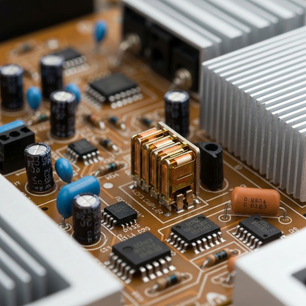
Locate the optocoupler on the power supply board. It's usually a small 4-pin IC near the secondary side voltage divider resistors. The PC817 is a common part. It has an LED on the input side (connected to secondary voltage) and a phototransistor on the output side (connected to the PWM controller IC).
Test the Optocoupler
Desolder the optocoupler and test it out of circuit. Test the LED side (pins 1-2) with diode mode - should show 1.1-1.3V forward drop. Test the transistor side (pins 3-4) - should show high resistance. Now apply 5V through a 1kΩ resistor to the LED and measure resistance across the transistor - it should drop to a few hundred ohms. If the transistor doesn't switch, the optocoupler is dead.

Replace the Optocoupler
Install a new PC817 or EL817. Pay attention to pin 1 orientation (usually marked with a dot). Solder it in place. Double-check your work - a backwards optocoupler can damage the controller IC.
Test and Power On
Reassemble the power supply board. Plug in the TV and power it on. The standby light should illuminate immediately. Measure the secondary voltage rails - they should all be within spec. The TV should boot normally. This $0.50 part just saved an $800 TV.

Conclusion
The optocoupler is a critical but often overlooked component in switching power supplies. It provides electrical isolation between the high-voltage primary side and the low-voltage secondary side while allowing the feedback signal to pass through optically. When it fails, the power supply has no way to regulate its output and shuts down completely. This is a common failure in TVs that are 5+ years old. Total repair cost: under $1.