Skyworth 65" HDTV - Power Supply Rebuild
Skyworth 65SUC9300 with intermittent power issues. Complete power supply capacitor replacement using ESR testing and preventive maintenance techniques.
Symptoms
- TV turns on intermittently (sometimes works, sometimes doesn't)
- High-pitched whining noise from power supply
- Standby light flickers
- TV shuts down randomly after 10-30 minutes
Diagnosis
Customer reported the TV had been getting progressively worse over 6 months. Initial voltage testing showed the 12V rail fluctuating between 11.2V and 12.8V under load - should be stable at 12V ±5%. The 5V standby rail was also unstable. Used an ESR (Equivalent Series Resistance) meter to test all electrolytic capacitors on the secondary side of the power supply. Found 6 out of 12 capacitors reading above 5Ω ESR (should be under 1Ω for low-ESR caps). High ESR causes ripple voltage, inefficiency, and heat. Visual inspection also revealed slight bulging on two capacitors. The root cause was cheap 85°C rated capacitors failing after 4 years of thermal stress.
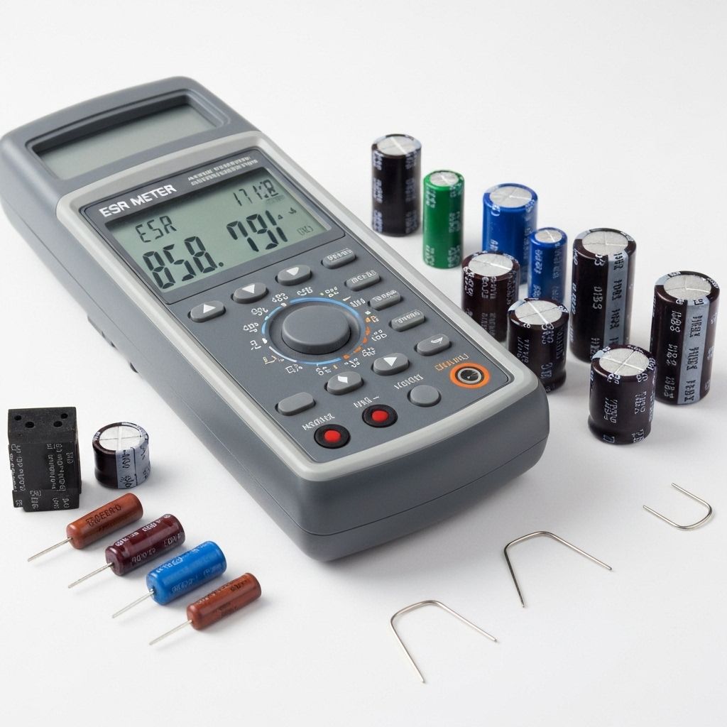
- ESR Meter (Essential for this repair)
- Multimeter (DC voltage testing)
- Soldering Iron 60W+
- Desoldering Pump
- Flux Pen
- Wire Cutters
- Oscilloscope (optional, for ripple testing)
- Capacitor Kit - Low ESR 105°CComplete set for Skyworth PSUIncludes 1000µF 16V, 470µF 25V, 220µF 35V
- Individual CapacitorsNichicon or Panasonic brandIf kit unavailable, use premium Japanese brands
Repair Process
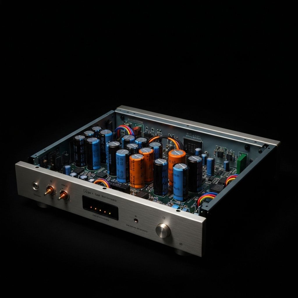
Safety and Initial Testing
Unplug TV and wait 15 minutes for capacitors to discharge. Remove back cover and locate the power supply board (where AC cord connects). With the TV plugged in and powered on, carefully measure the voltage rails: 12V, 5V, and 3.3V. Note any fluctuations or out-of-spec readings. Power off and unplug before proceeding.
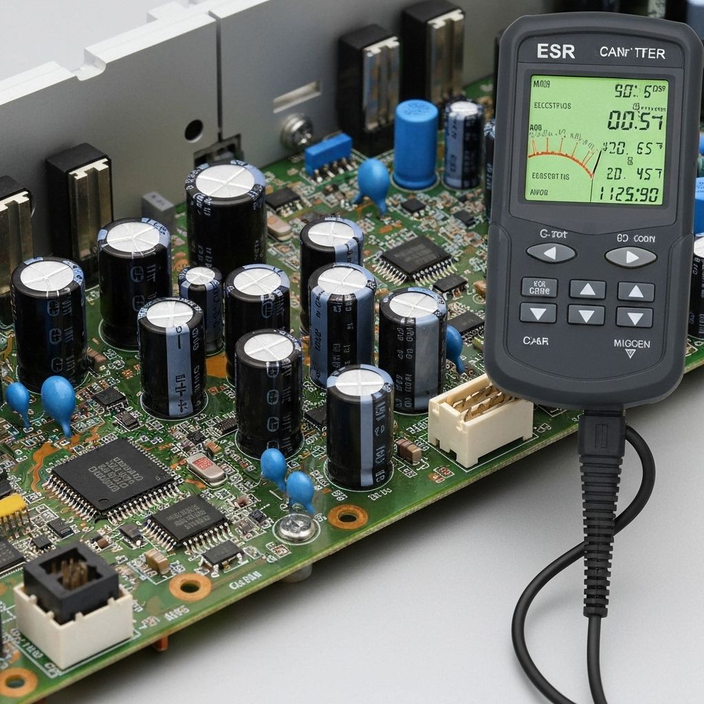
ESR Testing to Identify Bad Capacitors
This is the key diagnostic step. With the TV unplugged, use an ESR meter to test each electrolytic capacitor IN-CIRCUIT (no need to desolder). Touch the probes to the capacitor leads. Good low-ESR caps should read under 1Ω. Anything above 3-5Ω is failing. Mark all bad capacitors with tape. In this repair, we found 6 capacitors with ESR readings between 8-15Ω.
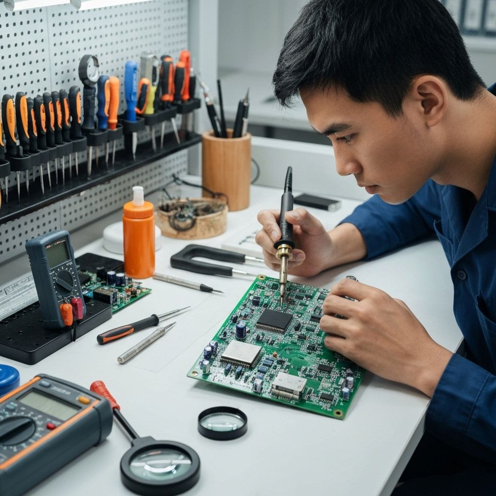
Document and Remove Failed Capacitors
Take a photo of the board for reference. Note the polarity of each capacitor (the stripe indicates negative). Desolder the bad capacitors. Pro tip: Add fresh solder to the joints first to help the old lead-free solder flow better. Use a desoldering pump to clear the holes completely.
Install Premium 105°C Capacitors
Install the new capacitors, paying close attention to polarity. The stripe on the capacitor body must align with the shaded area on the PCB silkscreen. Use 105°C rated capacitors - they cost slightly more but will last 2-3x longer than the original 85°C parts. Solder them in and trim the leads flush.

Test and Verify Repair
Reassemble the TV and power it on. Measure the voltage rails again - they should now be rock solid. The 12V rail measured a stable 12.04V with minimal ripple. The whining noise was completely gone. Let the TV run for 1-2 hours to ensure stability. Optionally, use an oscilloscope to check for AC ripple on the DC rails - should be under 50mV peak-to-peak.

Conclusion
The power supply now operates flawlessly with stable voltage rails and no noise. The use of 105°C low-ESR capacitors ensures this repair will outlast the original design. Total cost of parts was under $15, compared to a $120 replacement power supply board. This is a preventive maintenance repair that can be done on any aging TV to extend its life significantly.